Alarms
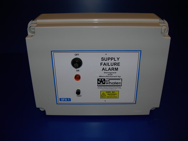
SFA1
This simple emergency detector operates an output relay that supplies a 12V d.c. Output supply to drive a hooter when either an over-temperature or public electricity supply fails the 12 d.c. supply is provided by an internal battery that is maintained in a readiness state by the incorporated trickle charger circuit. Hooter will remain operating untill mains a.c. supply returns or internal battery dischargers. A test button is provided for weekly testing the alarm system.
SFA2
Magnetically retained doors are maintained in position by 24V d.c. supply until public electricity fails or an over – temperature is detected. Immediately an emergency prevails, the output hooter relay supplies 12 and 42V d.c. to output terminals for connection to an appropriate hooter. Hooter remains operating unitl a.c. supply returns or internal battery discharges. The 24V internal battery is maintained in a readiness state by a trickle charger. A test button is provided for weekly testing of the alarm system.
SFA3
The SFA 3 is a larger version of the SFA2. It has all the same features as the SFA2 but will operate more magnets and is fitted into a larger box.
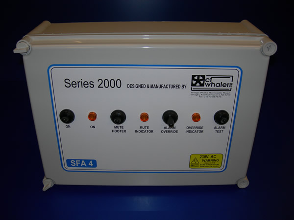
SFA4
The SFA 4 Auto Dialler system provides when fault occurs, automatic telephone dialling of pre-programmed numbers. There is an adjustable time delay between the commencement of a fault and the starting of the Auto Dialling Sequence. When a fault occurs due to a mains failure or over temperature etc. Either relay or thermostat contacts within the alarm circuit will open. This will immediately cause activation of the hooter or flashing beacon. after an adjustable time delay (maximum 3minutes) the Auto Dialler will activate and inform a central station that a fault has occured at your specific location. If the fault is due to a complete mains failure the SFA4 will still function due to its own internal power source provided by a rechargeable battery.
SFA 4 Red Care
The SFA 4 Red Care unit has the same operating functions as the SFA 4 however the Red Care Unit has a different operating circuit board which provides a secure communication link between the alarm system at the premises and the central station.
SFA D
Up to 8 individual channels of detection of various devices i.e. thermostat contacts, intruder switches that open circuits upon dangerous conditions prevailing etc. Used for high and low temperatures, public electricity supply failures, building unauthorised intrusion and high or low water or feed supply conditions. Fault causes operation of output relay contacts and individual LEDs indicate faulty channel or where over ride is applied. Reset is provided by a simple push button. 16 and 24 Channels are available if required.
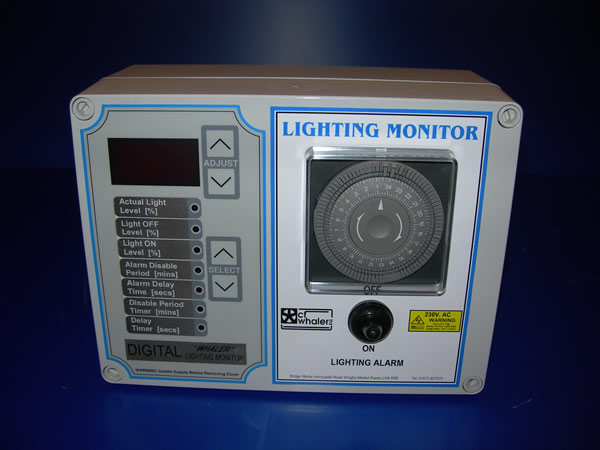
Lighting Monitor/Alarm
This unit is designed for use particularly with laying birds either for egg production or breeder houses or even rearing units where lighting patterns are critical. One slip up with the setting of a time clock or a blown fuse in a row of lights can upset egg production for a number of days or delay bird maturity in the case of rearing.
The lighting monitor/alarm senses the actual level of light in the poultry house with a photo cell and detects if the level falls outside that expected at any time during the 24 hour period. If for instance the lights were to fail to turn off at the normal set time, the light detector in conjunction with the built in time clock would signal an alarm.
The Lighting Monitor will detect the following:
- Lights remaining ON when they should be OFF
- Lights staying OFF when they should be ON
- Dimmer units set wrong or malfunctioning
- Lanes left on manual ON or OFF
- Blown fuses or tripped circuit breakers within the lighting circuit


